Tool Location
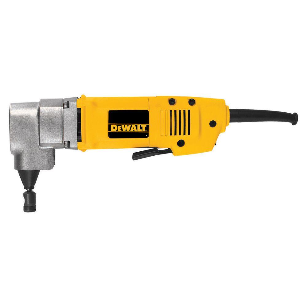
Waterjets
Tool Type
Software
Additional Information
One Page Tool Reference Sheet
Overview
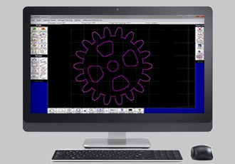
Omax Layout is a 2D CAD software that creates toolpaths for Omax Waterjets. Layout provides the tools necessary to import 2D CAD files, such as .dxf, and process them for use with the Omax Maxiem 1515 and Protomax waterjet. Some of these tools include cleaning imported files for pathing errors, generating toolpaths, detecting defects and dangerous features, and even drawing extra shapes to supplement the cut.
How To Use This Tool
Click on the Omax layout icon in the taskbar at the bottom of the monitor and click File > Import and select the desired file.
Find the desired file using the File Explorer, right click, and select Open With Omax Layout.
Note: for the software uses below, it is helpful to view the attached reference files to navigate the Omax Layout interface
- Open the desired file(s) in Omax Layout using the startup procedure above. Make sure the filetype is .dxf
- On the right menu bar, click “Clean.” On the pop up menu, make sure “Remove Unecessary Dots” is selected. Then click “Start”.
- For reference, each grid square is 1 sq. inch; use this to determine whether your part is the right scale. If not, right click on the “Select” button in the upper left bar, and “Select All.” Then click on the “Size” button in the same menu bar and enter the scale factor.
Note about the Select Tool: The default selector selects single lines. To select a window, right click on “Select” and click on “Window.”
- If the file is not fully on the grid, Select all using the instruction above, and select the “Move” button to move the model. Click and release on the model, this defines a starting location. Do not click and hold the mouse button. Then click and release on the final location; Layout should preview the final location on the model as you do this.
- Rotate the files by selecting the model to rotate and using the rotate button. Again, click and release on the model for the initial position, and click and release for the final position. A numerical angle can also be specified in the menu that appears on the bottom of the screen.
- Right click on the quality button on the bottom menu bar and click on “All.” Select the desired cut quality. 5 is the highest quality of cut, but also takes the longest. Generally, 3 should suffice for most cuts.
- Right click on “Lead I/O” and select “Autopath (Advanced and Configure).” On the diagram to the left, select the starting and ending points. The green dot is the start, while the red dot is the terminus. Then click OK.
- Green traverse lines and small orange lead in/outs should have been generated.
- Right click on “Lead I/O” and select “Create tab”. Hover the cursor near the desired location of the tab. When the tab appears, click to secure its location.
- Right click on “Path.” In the right menu bar. Select “Automatically generate.” On the pop up diagram, Click on/near the starting point.
- The path should automatically generate and a preview should appear. If there are errors, please refer to the Troubleshooting section below.
- Make sure that the kerf of the path is on the correct side of the cut lines. If not, then reject the path and make sure the model is clean. If the problem persists, please refer to the Troubleshooting section below.
- If the path is correct, click Save. Then right click on “Path” and open ORD path in Make.
- Continue the process in the Make software.
- When creating files for use with the waterjet, make sure the filetype is .dxf. Other 2D CAD files do not work as well with importing.
- When generating .dxf files, good practice is to use CAD software to fully define the edges first. This helps eliminate discontinuities, loops and other defects. If using a vector design software, like inkscape. Make sure any corners or junctions between lines are fully connected and smooth (no loops).
- In the “Clean” diagram menu, increase or decrease the threshold to either include smaller features, or delete larger ones.
- If the path still appears on the wrong side, right click on the “Path” button and select Custom Toolpath options. In the pop-up diagram, select the Kerf offset and accept the changes. Then try re-pathing the model.
- Zoom in where the errors occur, if the error is a loop, use the selector tool to delete the loop and clean the diagram again.
- If the error is a disconnect, use the line tool to connect the discontinuity.
- If the error is the kerf offset on the wrong side, and basic troubleshooting did not work, use draw a box around the model, and set a cut quality of 3. Then repath.
- The last manual solution is to click Path > Custom Toolpath Options. Then select “ask me at each opportunity” to run through the cut and manually select the kerf offset.
- For additional preprocessing, open the file in a 3D CAD software such as Fusion 360, and make sure the paths are fully defined.
References:
Omax. (n.d.). Omax Layout. Retrieved July 7, 2018 from https://knowledgebase.omax.com/protomax/content/wh-protomax/layout/help_contents.htm
Omax. (n.d.). Omax Layout. Retrieved July 7, 2018 from https://www.omax.com/software/layout
Author Information
Article was written by Siddharth Salnuke, and edited by Veronica Spencer.
Last Updated: August 12 2018.